

Why Choose a 30-60kA AC Lightning Surge Arrester for Reliable Power Protection?
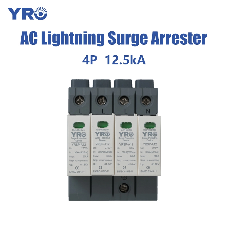
Article Summary: Lightning strikes and electrical switching operations can expose AC power distribution systems to dangerous transient overvoltages. A 30-60kA AC lightning surge arrester is designed for demanding surge protection applications, helping divert excessive transient current and reduce the risk of damage to electrical equipment. However, selecting the right arrester involves more than comparing its kA rating. Voltage compatibility, discharge current waveform, protection level, installation position, grounding quality, and applicable standards all influence actual protection performance. This guide explains how 30-60kA AC surge arresters work, why their current ratings matter, and how industrial buyers can evaluate the right solution for their electrical systems.
Article Outline
- Understanding the purpose of a 30-60kA AC lightning surge arrester
- How lightning and switching surges threaten electrical systems
- Why 30-60kA discharge capacity matters
- Understanding the key technical parameters
- Common applications and installation locations
- How to choose the right AC lightning surge arrester
- Installation and maintenance considerations
- Common purchasing mistakes to avoid
- Frequently asked questions
Table of Contents
- Why Is a 30-60kA AC Lightning Surge Arrester Important?
- How Do Lightning Surges Damage AC Electrical Systems?
- Why Does the 30-60kA Rating Matter?
- Which Technical Parameters Should Buyers Understand?
- Where Are 30-60kA AC Surge Arresters Commonly Used?
- How Can You Select the Right Surge Arrester?
- What Installation Factors Affect Protection Performance?
- How Can You Maintain Long-Term Protection Reliability?
- What Purchasing Mistakes Should Buyers Avoid?
- Frequently Asked Questions
Why Is a 30-60kA AC Lightning Surge Arrester Important?
Modern electrical installations depend on a stable power supply to keep production equipment, automation systems, communication devices, and commercial facilities operating efficiently. Yet even a well-designed electrical network can be exposed to sudden voltage surges caused by lightning activity or switching operations.
These transient events may last only a very short time, but their effects can be serious. Sensitive electronic components may fail, insulation systems may deteriorate, and unexpected equipment shutdowns can interrupt production. For industrial facilities, the resulting maintenance costs and operational losses can be considerably greater than the initial investment in surge protection.
A 30-60kA AC lightning surge arrester provides a protective path for excessive transient current. When a surge occurs, the arrester changes its electrical behavior to divert the surge toward the grounding system and limit the voltage appearing across protected equipment.
The 30-60kA range is commonly associated with surge protection devices designed for demanding distribution environments. Nevertheless, buyers must identify whether this figure represents nominal discharge current (In), maximum discharge current (Imax), or lightning impulse current (Iimp). These ratings use different test waveforms and cannot be treated as interchangeable.
Key takeaway: An effective surge protection solution is not simply the product with the largest kA number. It is the device whose electrical ratings, protection characteristics, and installation conditions match the actual requirements of the power distribution system.
How Do Lightning Surges Damage AC Electrical Systems?
Understanding the sources of transient overvoltage helps buyers determine why surge protection is necessary and where protective devices should be installed.
2.1 Direct and nearby lightning strikes
A direct lightning strike can introduce extremely high-energy current into a building or electrical installation. Even when a structure has an external lightning protection system, part of the lightning current may enter the electrical network through grounding connections and other conductive paths.
Nearby lightning strikes can also create electromagnetic fields that induce transient voltages in power cables. These disturbances may travel through electrical distribution networks and reach equipment located some distance from the original strike.
2.2 Switching operations
Not all electrical surges come from lightning. Switching large motors, transformers, capacitors, and industrial loads can generate transient overvoltages. These events may occur repeatedly during normal equipment operation.
2.3 Power system disturbances
Grid disturbances, sudden load changes, and certain fault conditions can also expose electrical components to abnormal voltage conditions. Although not every abnormal voltage event is a transient surge, proper system protection requires understanding the different risks involved.
| Surge Source | Potential Impact | Protection Consideration |
|---|---|---|
| Direct lightning | High-energy lightning current entering the installation | Evaluate Type 1 protection and lightning current requirements |
| Nearby lightning | Induced transient voltage in power cables | Evaluate Type 2 protection and coordination |
| Switching operations | Repeated transient disturbances | Choose suitable discharge capacity and voltage protection level |
| Grid disturbances | Abnormal electrical conditions and possible equipment stress | Assess surge protection alongside other power system protections |
Why Does the 30-60kA Rating Matter?
The discharge current rating indicates the surge current that a protective device is designed and tested to handle under specified conditions. A higher rating can provide greater discharge capability, but the meaning of the rating must be checked before comparing different products.
3.1 Nominal discharge current (In)
Nominal discharge current is measured using an 8/20 μs current waveform. It describes the peak current that a Type 2 surge protective device can discharge under its specified test conditions. This parameter is particularly relevant when comparing devices intended to protect distribution boards against induced lightning and switching surges.
3.2 Maximum discharge current (Imax)
Maximum discharge current is also associated with an 8/20 μs waveform for Type 2 SPDs. It represents the maximum single-discharge capability declared under the applicable test conditions. It should not be confused with the nominal discharge current rating.
3.3 Lightning impulse current (Iimp)
For Type 1 surge protective devices, lightning impulse current is evaluated using a 10/350 μs waveform. This waveform represents a higher-energy lightning current impulse and is used to assess the device's ability to handle partial direct lightning currents.
| Parameter | Typical Test Waveform | What It Indicates |
|---|---|---|
| In | 8/20 μs | Nominal discharge capability |
| Imax | 8/20 μs | Maximum discharge capability for Type 2 SPD |
| Iimp | 10/350 μs | Lightning impulse current capability for Type 1 SPD |
For example, a product advertised as 60kA may have a 60kA Imax rating rather than a 60kA In or Iimp rating. These products do not necessarily offer equivalent performance. Industrial buyers should request the complete technical datasheet and verify the waveform, test category, and rating for each protection mode.
Important purchasing tip: Always ask suppliers to identify exactly what the 30kA, 40kA, 50kA, or 60kA figure represents. A clear distinction between In, Imax, and Iimp prevents incorrect technical comparisons.
Which Technical Parameters Should Buyers Understand?
Besides discharge current, several electrical characteristics determine whether an AC lightning surge arrester is suitable for a particular installation.
4.1 Maximum continuous operating voltage (Uc)
Uc is the maximum AC voltage that can be continuously applied to the SPD under its specified operating conditions without causing it to enter its surge-limiting state. The selected value must match the system voltage, grounding arrangement, and applicable design requirements.
4.2 Voltage protection level (Up)
Up describes the declared voltage-limiting performance of the surge protective device under specified test conditions. A lower protection level generally offers better voltage limitation, provided the device is correctly selected and coordinated with the equipment's impulse withstand capability.
4.3 Protection type
Different SPD types are designed for different locations and surge exposure levels.
- Type 1: Designed to discharge partial lightning current and commonly installed at the service entrance or main distribution board where lightning current protection is required.
- Type 2: Designed for protection against induced lightning surges and switching overvoltages, commonly installed in main or sub-distribution boards.
- Type 3: Provides additional protection close to sensitive terminal equipment and is generally used as part of a coordinated protection system.
- Type 1+2: Combines the functions of Type 1 and Type 2 protection in one device, subject to its declared ratings and application requirements.
4.4 Poles and electrical system compatibility
The number of poles and connection configuration must match the electrical network. Common arrangements include 1P, 2P, 3P, 3P+N, and 4P configurations. Buyers should also consider whether the installation uses TN-S, TN-C, TT, or another grounding arrangement.
4.5 Additional technical characteristics
| Specification | Why It Matters |
|---|---|
| Rated system voltage | Ensures compatibility with the AC power network |
| Frequency | Confirms suitability for 50Hz or 60Hz systems |
| Short-circuit current rating | Helps determine suitability under specified fault conditions |
| Backup fuse requirement | Ensures correct coordination with upstream protection |
| Operating temperature | Determines suitability for the installation environment |
| Remote signaling | Supports remote monitoring of device status when provided |
| Enclosure protection | Helps evaluate suitability for the intended installation location |
Where Are 30-60kA AC Surge Arresters Commonly Used?
30-60kA surge protection solutions may be considered in electrical installations where transient overvoltage exposure and equipment replacement costs justify a suitable level of protection. The exact rating must be determined by the system design rather than by application name alone.
5.1 Industrial manufacturing facilities
Manufacturing plants contain motors, programmable logic controllers, control cabinets, production lines, and automated equipment. Surge disturbances can interrupt production and affect electronic control components. Properly coordinated SPDs help reduce these risks.
5.2 Commercial buildings
Office buildings, shopping centers, hotels, and large commercial complexes rely on electrical distribution systems for lighting, elevators, HVAC equipment, security systems, and communication infrastructure. Surge protection helps improve the resilience of these installations.
5.3 Solar and renewable energy facilities
AC-side surge protection can be an important part of photovoltaic and renewable energy installations. Inverter AC outputs, distribution cabinets, and grid connection points may require suitable protection against transient overvoltages. DC-side protection must be evaluated separately using devices specifically designed for the relevant DC voltage and application.
5.4 Data centers and communication infrastructure
Data centers depend on stable electrical power to support servers, network equipment, cooling systems, and backup power infrastructure. A coordinated surge protection strategy can help reduce unexpected damage and improve system availability.
5.5 Infrastructure and utility projects
Water treatment plants, transportation facilities, pumping stations, and other infrastructure installations may operate equipment in exposed electrical environments. Selecting appropriate surge protection helps support reliable long-term operation.
How Can You Select the Right Surge Arrester?
Choosing the right product requires evaluating the entire electrical installation rather than focusing on a single discharge current specification. The following process can help engineering teams, electrical contractors, and procurement departments make more informed decisions.
Step 1: Identify the electrical system
Confirm the rated voltage, frequency, number of phases, grounding arrangement, and distribution configuration. For example, a three-phase 400V AC system and a single-phase 230V AC system may require different SPD configurations.
Step 2: Assess the lightning exposure
Determine whether the building has an external lightning protection system, whether overhead power lines are involved, and whether the installation is located in an area with significant lightning activity. These factors influence the required SPD type and impulse current capability.
Step 3: Determine the required discharge ratings
Compare In, Imax, and Iimp based on the selected protection category and applicable design standards. Avoid comparing products using kA values without checking their test waveforms.
Step 4: Check the voltage protection level
Ensure the selected Up is compatible with the impulse withstand voltage of the equipment being protected. Additional protection stages may be necessary for sensitive electronic devices located downstream.
Step 5: Evaluate installation and coordination requirements
Check the available installation space, connection configuration, conductor requirements, upstream overcurrent protection, and coordination with downstream SPDs.
Step 6: Review documentation and product compliance
Request technical datasheets, test reports, product identification, applicable certification documents, and installation instructions. For low-voltage AC SPDs, IEC 61643-11 is an important product standard to consider. Installation design should also follow the relevant local electrical regulations.
| Selection Factor | Buyer Checklist |
|---|---|
| Electrical compatibility | Rated voltage, frequency, phases, and grounding system |
| Surge capacity | Verified In, Imax, or Iimp with the corresponding waveform |
| Protection performance | Suitable Up and coordinated protection stages |
| Product configuration | Poles, wiring arrangement, and mounting requirements |
| Safety requirements | Short-circuit rating and specified backup protection |
| Supplier reliability | Technical documentation, quality control, and after-sales support |
What Installation Factors Affect Protection Performance?
Even a high-capacity surge protective device cannot deliver its intended performance if it is installed incorrectly. Proper installation is essential for reducing residual voltage and ensuring that surge current has an effective path to the grounding system.
7.1 Keep connecting conductors short
Long connecting conductors introduce additional inductive voltage during fast transient events. Therefore, the total connection path between the SPD, live conductors, and grounding system should be kept as short and direct as practicable, following the manufacturer's instructions and applicable installation standards.
7.2 Ensure effective grounding
The SPD relies on the electrical installation's grounding and bonding arrangement to divert surge current safely. Poor grounding connections, loose terminals, or excessive conductor impedance can reduce overall protection effectiveness.
7.3 Coordinate upstream and downstream devices
In multi-stage protection systems, SPDs should be coordinated so that each device operates within its intended surge exposure and energy-handling capability. Installing several devices without considering coordination may result in ineffective protection.
7.4 Follow the correct wiring diagram
Connection methods differ depending on the SPD design and grounding arrangement. Incorrect connections may compromise protection or create safety risks. Installation should always be performed by qualified electrical professionals.
Installation reminder: Surge protective devices are not substitutes for circuit breakers, fuses, grounding systems, or external lightning protection systems. They work as part of a coordinated electrical safety strategy.
How Can You Maintain Long-Term Protection Reliability?
Surge protective devices may deteriorate after repeated exposure to transient events. Environmental conditions, electrical faults, and component aging can also affect their operating condition.
Regular inspection helps identify potential problems before they lead to unexpected equipment downtime.
- Check status indicators: Review the visual status window or indication mechanism provided by the manufacturer. Follow the specific meaning of each indicator color.
- Inspect terminals: Look for loose connections, corrosion, discoloration, or signs of overheating during an appropriate maintenance shutdown.
- Review remote alarms: Where remote signaling is available, verify that monitoring and alarm functions operate correctly.
- Check environmental conditions: Ensure the installation environment remains within the product's specified temperature and humidity limits.
- Replace damaged devices: Replace SPDs that have reached their end-of-life indication or show signs of damage, following manufacturer instructions.
- Keep maintenance records: Document inspections, replacement dates, and any known surge events.
Maintenance intervals should be determined by the installation's risk assessment, operating environment, manufacturer recommendations, and applicable regulations. A device with a normal status indication should not automatically be assumed to provide complete protection under every possible condition.
What Purchasing Mistakes Should Buyers Avoid?
Industrial buyers often compare surge arresters based on price and headline discharge current. However, several overlooked details can result in products that do not meet the actual project requirements.
Mistake 1: Comparing different current ratings
A 60kA Imax product is not equivalent to a 60kA Iimp product. Always compare the same parameter and waveform.
Mistake 2: Ignoring the system voltage
Choosing an unsuitable Uc can result in unwanted operation or inadequate protection. Confirm system voltage and grounding conditions before ordering.
Mistake 3: Selecting an SPD based only on price
A lower purchase price may not provide the documentation, protection characteristics, or service support required for a demanding project. Evaluate total value rather than initial cost alone.
Mistake 4: Overlooking certification and test documentation
Product specifications should be supported by appropriate technical documents and test evidence. Buyers should verify the exact model and its declared performance rather than relying only on general marketing descriptions.
Mistake 5: Neglecting installation conditions
Correct ratings cannot compensate for poor wiring, unsuitable grounding, or incorrect coordination. Product selection and installation engineering must be considered together.
For international distributors, panel builders, contractors, and OEM customers, working with a manufacturer that can provide clear technical communication and consistent product documentation can make procurement and project implementation more efficient.
Frequently Asked Questions About 30-60kA AC Lightning Surge Arresters
1. What does 30-60kA mean in an AC lightning surge arrester?
It refers to a current rating expressed in kiloamperes. Depending on the product, it may indicate nominal discharge current (In), maximum discharge current (Imax), or lightning impulse current (Iimp). Buyers should confirm the exact parameter and test waveform in the datasheet.
2. Is a 60kA surge arrester better than a 30kA model?
Not necessarily. A higher rating may indicate greater discharge capacity for the same test parameter and waveform, but the best choice depends on the installation's lightning exposure, electrical system, protection type, and required voltage protection level.
3. What is the difference between Type 1 and Type 2 surge arresters?
Type 1 devices are tested using a 10/350 μs lightning impulse current waveform and are designed to handle partial lightning current. Type 2 devices are tested using an 8/20 μs waveform and are generally used to protect distribution systems against induced lightning and switching surges.
4. Can a 30-60kA AC surge arrester protect sensitive electronic equipment?
It can form part of a coordinated protection system. However, sensitive equipment may require additional downstream Type 2 or Type 3 protection, depending on the installation layout and equipment withstand voltage.
5. Is an AC surge arrester suitable for solar DC systems?
An AC SPD should not be used as a substitute for a DC-rated SPD. Photovoltaic DC circuits require surge protection devices specifically designed for their DC voltage, polarity, and operating conditions. AC-side and DC-side protection should be evaluated separately.
6. Does a surge arrester need a grounding connection?
Yes. Its protective function depends on an appropriate connection to the installation's grounding and bonding system. The connection must follow the manufacturer's wiring instructions and applicable electrical regulations.
7. Which standard should buyers check for low-voltage AC SPDs?
IEC 61643-11 is an important product standard for low-voltage surge protective devices connected to AC power systems. Buyers should also check applicable national or regional requirements and installation standards.
8. How often should an AC surge arrester be inspected?
Inspection frequency depends on the installation environment, lightning exposure, manufacturer recommendations, and applicable regulations. Regular visual status checks and scheduled electrical maintenance are recommended.
9. Can one surge arrester protect an entire industrial facility?
One device may provide protection at a specific distribution point, but a large facility often requires a coordinated multi-stage SPD arrangement. Protection should be designed according to the electrical distribution layout and equipment sensitivity.
10. What information should I provide when requesting a surge arrester quotation?
Provide the rated AC voltage, system frequency, number of phases, grounding arrangement, required SPD type, discharge current parameters, pole configuration, installation location, and any certification or project-specific requirements. This information helps the supplier recommend a suitable product.
Choose Reliable AC Surge Protection for Your Electrical Projects
Protecting electrical equipment starts with selecting a surge protection solution that matches the real operating conditions of your installation. From discharge current capacity and voltage protection level to product configuration and technical documentation, every specification plays an important role in long-term reliability.
ZHEJIANG YRO NEW ENERGY CO., LTD is committed to providing surge protection solutions for electrical distribution and renewable energy applications. Whether you are an electrical equipment distributor, panel builder, EPC contractor, or industrial procurement professional, choosing the right product begins with understanding your project requirements.
Looking for a suitable 30-60kA AC Lightning Surge Arrester for your next project? Contact us to discuss your voltage requirements, protection configuration, technical specifications, and product inquiries. Our team can help you evaluate a suitable solution for your application.
Contact us today to request product information, technical documentation, and a quotation for your AC surge protection requirements.