

Why Are Solar Isolator Switches for Solar Power Systems Indispensable for Overseas PV Projects?
As solar energy continues to grow worldwide, photovoltaic (PV) projects demand higher safety standards. One critical component is the Solar Isolator Switch. This article explains why overseas PV projects cannot do without it.
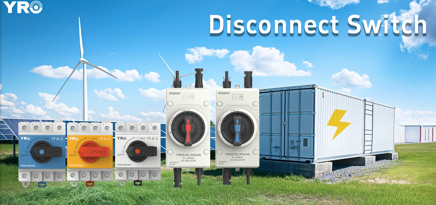 1. What Roles Do Solar Isolator Switches Play in PV Projects?
A Solar Isolator Switch is a safety device that manually disconnects the direct current (DC) electricity from the solar PV system . It allows for the safe isolation of DC power generated by solar panels.
Safety for Installers and Maintenance Personnel
Solar panels generate electricity whenever they are exposed to sunlight. They can produce high-voltage DC even when the grid is off. An isolator switch ensures that technicians can safely work on the system without live electrical hazards. A PV string can present voltage whenever there is light, even when the inverter is not producing AC output .
Fire Prevention
Faulty wiring or component failures can lead to electrical fires. A properly rated isolator switch helps cut off power in emergencies, reducing fire risks.
Compliance with Electrical Standards
Most countries mandate the use of isolator switches in solar installations to comply with safety regulations. These include IEC 60947, NEC Article 690 in the U.S., and AS/NZS 5033 in Australia. The Australian Standard AS/NZS 5033 mandated the installation of rooftop solar isolator switches . For international projects, DC isolation is often specified and verified within IEC/EN-aligned design and documentation processes . A common baseline is to use switch-disconnectors compliant with IEC/EN 60947-3 .
System Maintenance and Troubleshooting
Isolating parts of the system allows for easier diagnostics and repairs without shutting down the entire PV array. A local isolator supports a repeatable procedure that reduces the likelihood of accidental contact, connector damage, or switching events at inappropriate points in the circuit .
Installation Locations
Solar Isolator Switches are usually located close to the solar panels on the roof and close to the DC end of the inverter . This means the panels can be disconnected both on the ground and on the roof . An inverter isolator switch should be installed on the DC side of the solar system, specifically between the PV array and the inverter .
2. The Hidden Risks Without Solar Isolator Switches
Without a reliable isolation point, technicians are more likely to improvise. Common unsafe practices include:
Disconnecting DC Connectors Under Load
Without proper isolation, technicians may pull apart DC connectors while the circuit is still live. This increases arc risk and may create latent failures that later show up as hot joints and damaged connectors .
Relying Only on Remote Shutdown
A remote shutdown does not create a visible local break. Without a defined open point, workers cannot confirm the circuit is truly de-energized before starting work .
The Difference Between “Off” and “Isolated”
When an inverter is disabled or not producing AC, DC voltage can still remain present from the array . This is not a safe condition for opening terminals. In contrast, when a DC circuit is opened at a PV-rated isolator, there is a defined open point at a known location, which supports a controlled maintenance workflow after verification .
DC Arcing Hazards
AC current naturally passes through zero points, making arcs easier to extinguish . DC current is continuous, creating sustained and dangerous arcs when disconnected . Standard AC switches lack the specialized arc-quenching mechanisms required for DC power. Using them in solar systems can cause severe overheating, melting, and serious fire hazards .
Risks from Poor-Quality Isolators
Poor-quality isolators may trip unnecessarily. Corrosion, especially in coastal areas, can lead to switch failure. Mechanical wear from frequent switching can degrade contacts over time. Moisture and chemical exposure can damage insulation, making it more conductive . Improper installation can result in electrical fires or system failures .
Emergency Scenarios
Emergencies create time pressure and imperfect information. A locally accessible isolation point allows responders and site personnel to establish a defined boundary without guessing which conductors remain energized .
3. How to Pick Reliable Solar Isolator Switches for Global Solar Installations
When selecting a Solar Isolator Switch for overseas PV projects, engineers should consider the following criteria:
Voltage and Current Rating
The switch must match or exceed the system’s maximum voltage and current. Engineers should calculate the worst-case cold Voc (open-circuit voltage) and continuous current basis, including any parallel-string current summation .
PV DC Arc Protection
DC arcs are harder to extinguish than AC arcs. The switch should have proper arc-quenching capabilities. A DC isolator switch suitable for PV is designed to open the circuit quickly and manage the arc that forms as contacts separate . The “safe break” is the combination of contact gap, insulation distances, mechanical switching speed, and arc control .
Weather Resistance and IP Rating
For outdoor installations, IP65 or higher ingress protection is recommended. An IP66 rating is vital for dust and water protection . Outdoor PV installations also impose UV and thermal stress, so enclosure materials need to tolerate long exposure and elevated temperatures .
Certifications and Compliance
Look for compliance with IEC, UL, TÜV, or other regional standards. For international projects, use switch-disconnectors compliant with IEC/EN 60947-3 . Compliance is achieved by selection plus documentation plus verification. It is not achieved by installing an unspecified switch .
Pole Configuration
Engineers should consider single-pole (for one conductor) or double-pole (for positive and negative DC lines). It is recommended to disconnect both DC conductors so maintenance teams have no ambiguity about the boundary .
Lockable OFF Position
A lockable OFF position supports maintenance isolation procedures . When the switch is in OFF, it opens the circuit and provides insulation and separation adequate for isolation when used within its rated conditions .
Clear ON/OFF Indication
A positive switching mechanism with clear ON/OFF indication helps technicians verify the switch state .
Key Selection Checklist
• Ratings: worst-case cold Voc, continuous current basis, and any parallel-string current summation
• Categories: PV DC duty classification appropriate for the circuit
• Placement: accessible location near the inverter with a documented isolation boundary
• Terminations: conductor range, ferrules/lugs, torque values, commissioning verification
• Environment: IP rating, UV resistance, temperature range, sealing and mounting method
• Documentation: Single Line Diagram (SLD) mapping, labels, commissioning records, and maintenance procedure notes
Inspection and Maintenance
Solar Isolator Switches should be inspected at least once a year . Maintenance focuses on checking for heat damage, moisture ingress, and the physical integrity of the enclosure . Technicians should also test the mechanical operation of the handle to ensure it has not become brittle or jammed .
4. Summary
Solar Isolator Switches are a small but crucial part of any solar power system. They ensure safety, compliance, and operational efficiency.
PV circuits can remain energized under illumination. DC switching requires purpose-built arc control. A PV-rated Solar Isolator Switch gives engineers and service teams a defined boundary they can operate, lock, and verify .
Overseas PV projects are commonly specified and verified against IEC and EN expectations. The isolation device must be suitable for PV DC duty, correctly rated for the system, and installed so technicians can operate it, verify the open state, and lock it out when required .